RLC message
| RLC Home : www.sharetechnote.com | ||||||||||||||||||||||||||||||||||||||||||||||||||||||||||||||||||||||||||||||||||||||||||||||||||||||||
Personally to me, RLC layer is one of the trickest area to understand in very detail. At the beginning it seems to be simple, but as I getting deeper and deeper into this layer I get more and more confused. Another difficulties is that I don't find any books or other training material explaining very detail on this area, whereas you would find a lot of books and materials digging very deeplyinto other layer.
Overview
As far as I experienced, there are three main topics we have to master on this layer to make our knowledge practical enough to the development or troubleshooting.
i) Understanding three types of RLC Mode : TM, UM, AM
ii) Segmentation (Splitting) and Concatenation (Combining) mechanism
iii) RLC Timers
I will not explain on these topics right now. It will be explained as you go along with this section.. but this part will be updated forever as I get more and more insight on this layer.
As in the section for other layer, let's start by "Reading (Verbalizing)" the pictures from the specification. The first diagram you will see in LTE RLC specification(TS 36.322) is as follows:
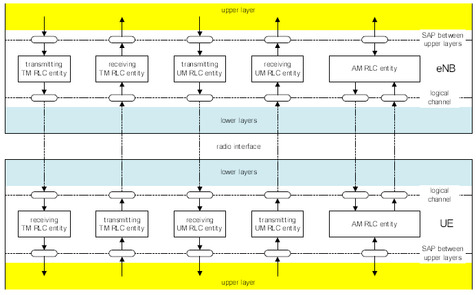
What do you read from the diagram above ? First you will see the layers labeled 'upper layer' and 'lower layer' ? What does these layer specifically mean ? 'Upper layer' in this case would mean 'RRC layer' or 'PDCP Layer' or in some case (especially in the simulation or testing environment' it can be a TE port ( a kind of data Input/Output port).
Then, in which case the upper layer should be RRC Layer and in which case it should be PDCP or TE port ? These are what you have to figure out as you go along this document.
And then.. you see another layer labelled 'lower layer'. What is the lower layer in this case ? It is simple. It means 'MAC' layer in most case.
There are another small issues that scared me.. it was the term 'entity' which sounded too abstract to me. (it may not be the case for others). I just take the term 'entity' as a kind of 'thread' or 'task' in software terminology. It may not be a perfect analogy but this terminology change made me much more comfortable when I am reading the specs.
What else you can read from the diagram above ?
One thing I notice is.. There are separate entity (thread or task) for Uplink and Downlink RLC for TM and UM. But in AM, both Uplink and Downlink path are merged into a single entity. Why ? This is also what you have to figure out later.
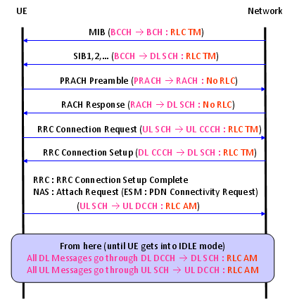
Another picture that I want you to keep in mind is shown below. Most of signaling message is using RLC and each of the message is a specific types of RLC mode, TM/UM/AM. Unlike the channel mapping, the association between each message and RLC type is not so tight meaning that network can allocate RLC types a little bit different from what is shown below, but I would say the following mapping would be a kind of 'Textbook' mapping.
As we go through this section, you will see the detailed behavior of each RLC mode. If you try to associate this diagram and the RLC description you will have more practical understanding of RLC and will help you greatly for protocol stack implementation and troubleshooting.
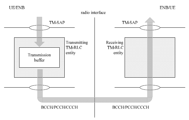
Overall Data Flow for TM RLC
For this section as well, let's start reading diagram from the specification.
Let's begin with TM mode. As you see in the following diagram, TM is the simplest RLC mode. TM stands for 'Transparent Mode'. The term 'Transparent' may have many different meaning. In this case, it would mean 'the contents goes through this layer without any modification'.
What does it mean by 'modification' ? In this context, it would mean
i) It does not add or remove any header to the input data
ii) It does not split the input data into multiple segment
iii) It does not combine the multiple input data into a single big chunk
The only operation operation being done in this mode is a buffering operation, but even this buffering operation is also very simple. It just keeps the input data for a certain amount of time or until next input data come in, it just discard it if it does not get transmitted within a certain time frame.
As you see in the diagram, BCCH, PCCH, CCCH goes through this type of RLC process. In WCDMA, Voice call traffic used this RLC mode as well. It means that even some type of DTCH (voice traffic) uses this mode in WCDMA. However it is technically possible to use TM mode for DTCH as well.
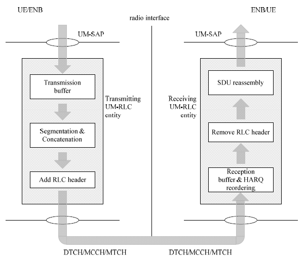
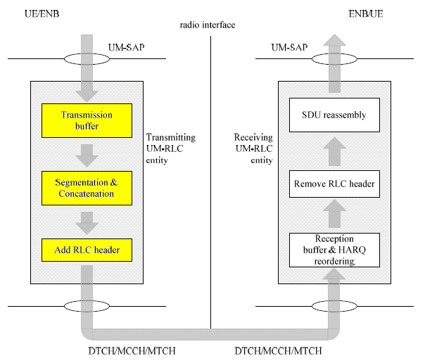
Overall Data Flow for UM RLC
Next, let's look into UM mode. UM stands for 'Unacknowledged Mode'. 'Unacknowledged Mode' means 'it does not require any reception response from the other party'. 'Reception response' simply mean 'ACK' or 'NACK' from the other party. (UM mode is similar to TM mode in that it does not require any ACK/NACK from the other party, but it is different from TM in that I has it's own header)
What is the difference between UM mode and TM mode we saw above ? It seems that UM mode is doing more operation than TM mode.
What kind of operation UM mode do ? You can just 'read' diagram for the answer. The answer would be a little bit different with transmitter side and reciever side.
Let's read the operation on transmitter side first. If you just read (vervalize) the diagram
i) Buffering
ii) Segmetation (Split a big chunk into a multiple small chunk)
iii) Concatenation (Combine a multiple small chunk into a large single chunk)
iv) Add RLC header (If you combine or split something, you have to be able to re-split or re-combine them into orignal chunk on the reciever side. For this, you have to put some tag(header) to those chunk)
Let's read the operation on transmitter side first. If you just read (vervalize) the diagram
i) Buffering
ii) Reordering (Sometimes the chunks transmitted earlier from transmitter may arrive late at the reciever. In this case you have to reorder the incoming chunks into proper order for reassembly).
iii) Remove the RLC header (you would remember that the transmitter put the header to each of the chunk. So you have to remove this before you reassemble the data).
iv) Reassembly
As you see, DTCH, MTCH. MCCH use this type of RLC process. Again, this is also a matter of choice. You can use AM or TM mode for DTCH.
Summary of RLC UM Data Flow - Transmission
i) Receive an Higher Layer Data (SDU) from PDCH or RRC
ii) Put the SDU into the transmission Buffer
iii) Segment or Concatenate the SDU into RLC PDU when MAC permit transmission
iv) Add a RLC header to the RLC PDU
v) Send the RLC PDU to the next layer (MAC)
Summary of RLC UM Data Flow - Reception
i) The MAC layer passes the received RLC PDU to the RLC layer.
ii) The RLC layer removes the RLC header from the PDU.
iii). The RLC layer assembles the PDUs into a upper layer SDU
iv). Pass the assembled SDUs to the PDCP or RRC layers.
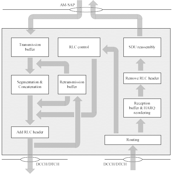
Overall Data Flow for AM RLC
Now let's look at AM mode which is the most complicated RLC type. 'AM' stands for 'Acknowledge Mode'. As it's name implies it requires ACK/NACK from the other party. It is more like TCP packet in IP world, whereas RLC UM is more like UDP in IP world.
Is it expecting the ACK/NACK for every transmission ? If it is the case, isn't it too much overhead ? Good question. Yes.. it is too much overhead. That's why we have RLC window concept (like TCP Window in IP traffic) and Polling bit concept and all sorts of ACK/NACK scheduling mechanism which makes it extremely difficult to understand full details of RLC AM operation. (This kind of detailed procedure would not be explained now.. but not sure by when I can get to the level of details -:)
Now just look into the diagram from the specification. If you go through the left column and the right colum, you will see the same procedures you saw in UM mode. so I don't want to verbalize that part again. What is different from UM mode lies in the middle column, namely 'Retransmission buffer' and 'RLC control' procedure.
Let's just follow the arrrows. What is coming into the retransmission buffer ? i.e, what is the input to the retransmission buffer ?
After RLC transmitter do the segmentation/concatenation process, it adds RLC header and then it creates two identical copies and transmit the one copy of the data out to lower layer (MAC) and send another copy to Retransmission buffer.
If the RLC get Nack or does not get any response from the other party for a certain period of time, the RLC packet (we call this RLC PDU) in the retransmission buffer gets transmitted again. If the RLC get ACK, the ones in retransmission buffer would be discarded.
Summary of RLC AM Data Flow - Transmission
i) Receive an Higher Layer Data (SDU) from PDCH or RRC
ii) Put the SDU into the transmission Buffer
iii) Segment or Concatenate the SDU into RLC PDU when MAC permit transmission
iv) Add a RLC header to the RLC PDU
v) Make a copy of the transmission buffer for a possible retransmission
vi) Send the RLC PDU to the next layer (MAC)
Summary of RLC AM Data Flow - Reception
i) The MAC layer passes the received RLC PDU to the RLC layer.
ii) The RLC layer removes the RLC header from the PDU.
iii) If the received RLC PDU does not have any problem, mark it as positive ACK (but whether the ACK is sent now or sometime later or omitted is determined by some other RLC parameters).
iv). The RLC layer assembles the PDUs into a upper layer SDU
v). Pass the assembled SDUs to the PDCP or RRC layers.
< Major Functions of RLC AM >
I think this list can give you another aspect of reading Figure 4.2.1.3.1-1 shown above. This is one way to learn new things. Try to describe it from many different perspective. There will be many things overlapped by multiple perspectives and there will be many things that looks different depending on the perspectives. It will help you to learn it in either ways. In some case, you will learn many things because they are similar and in other case you will learn things because they are different.
< Polling for RLC AM ARQ >
As I mentioned above, one of the most important feature for RLC AM is ARQ which is designed for reliable data traffic and the key factors for RLC ARQ are various Polling mechanism.
This mechanism involves two main part as follows :
i) Transmitter side : Poll Request
ii) Receiver side : Status Report carrying ACK, NACK etc
Now the question is to figure out the best timing/situation for Poll Request and the best timing/situation for Satus Report. Following is the list of several important factors to trigger for Poll Request and Satus Report. Following table is based on UMTS RLC AM operation and this triggering mechanism seems to get simpler in LTE. However I would list up more complicated case (UMTS case) to give you more detailed picture.
< Major RLC AM Parameters >
I think it will be helpful to look into some of high level RLC AM parameters (RRC parameters) and correlate these parameters with RLC AM operation process.
+-rrcConnectionSetup-r8 ::= SEQUENCE [0]
+-radioResourceConfigDedicated ::= SEQUENCE [100101]
| +-srb-ToAddModList ::= SEQUENCE OF SIZE(1..2) [1] OPTIONAL:Exist
| | +-SRB-ToAddMod ::= SEQUENCE [11]
| | +-srb-Identity ::= INTEGER (1..2) [1]
| | +-rlc-Config ::= CHOICE [explicitValue] OPTIONAL:Exist
| | | +-explicitValue ::= CHOICE [am]
| | | +-am ::= SEQUENCE
| | | +-ul-AM-RLC ::= SEQUENCE
| | | | +-t-PollRetransmit ::= ENUMERATED [ms5]
| | | | +-pollPDU ::= ENUMERATED [p4]
| | | | +-pollByte ::= ENUMERATED [kB25]
| | | | +-maxRetxThreshold ::= ENUMERATED [t1]
| | | +-dl-AM-RLC ::= SEQUENCE
| | | +-t-Reordering ::= ENUMERATED [ms35]
| | | +-t-StatusProhibit ::= ENUMERATED [ms35]
| | +-logicalChannelConfig ::= CHOICE [defaultValue] OPTIONAL:Exist
| +-drb-ToAddModList ::= SEQUENCE OF OPTIONAL:Omit
| +-drb-ToReleaseList ::= SEQUENCE OF OPTIONAL:Omit
| +-mac-MainConfig ::= CHOICE [explicitValue] OPTIONAL:Exist
| +-sps-Config ::= SEQUENCE OPTIONAL:Omit
| +-physicalConfigDedicated ::= SEQUENCE [1111001011] OPTIONAL:Exist
Just for your reference, I put WCDMA RLC parameters in Radio Bearer Setup message as follows.
+-SRB-InformationSetup-r7 ::= SEQUENCE [1]
| +-rb-Identity ::= INTEGER (1..32) [2] OPTIONAL:Exist
| +-rlc-InfoChoice ::= CHOICE [rlc-Info]
| | +-rlc-Info ::= SEQUENCE [1100]
| | +-ul-RLC-Mode ::= CHOICE [ul-AM-RLC-Mode] OPTIONAL:Exist
| | | +-ul-AM-RLC-Mode ::= SEQUENCE [1]
| | | +-transmissionRLC-Discard ::= CHOICE [noDiscard]
| | | | +-noDiscard ::= ENUMERATED [dat10]
| | | +-transmissionWindowSize ::= ENUMERATED [tw128]
| | | +-timerRST ::= ENUMERATED [tr550]
| | | +-max-RST ::= ENUMERATED [rst1]
| | | +-pollingInfo ::= SEQUENCE [010110] OPTIONAL:Exist
| | | +-timerPollProhibit ::= ENUMERATED OPTIONAL:Omit
| | | +-timerPoll ::= ENUMERATED [tp500] OPTIONAL:Exist
| | | +-poll-PDU ::= ENUMERATED OPTIONAL:Omit
| | | +-poll-SDU ::= ENUMERATED [sdu1] OPTIONAL:Exist
| | | +-lastTransmissionPDU-Poll ::= BOOLEAN [TRUE]
| | | +-lastRetransmissionPDU-Poll ::= BOOLEAN [TRUE]
| | | +-pollWindow ::= ENUMERATED [pw50] OPTIONAL:Exist
| | | +-timerPollPeriodic ::= ENUMERATED OPTIONAL:Omit
| | +-dl-RLC-Mode ::= CHOICE [dl-AM-RLC-Mode] OPTIONAL:Exist
| | | +-dl-AM-RLC-Mode ::= SEQUENCE
| | | +-dl-RLC-PDU-size ::= CHOICE [fixedSize]
| | | +-inSequenceDelivery ::= BOOLEAN [TRUE]
| | | +-receivingWindowSize ::= ENUMERATED [rw128]
| | | +-dl-RLC-StatusInfo ::= SEQUENCE [100]
| | | +-timerStatusProhibit ::= ENUMERATED [tsp120] OPTIONAL:Exist
| | | +-dummy ::= ENUMERATED OPTIONAL:Omit
| | | +-missingPDU-Indicator ::= BOOLEAN [TRUE]
| | | +-timerStatusPeriodic ::= ENUMERATED OPTIONAL:Omit
RLC Data Structure
Like any data structure, you would not completely understand this structure until you really construct this structure or analyze the structure with real data either in programming or in manually. Of course my recommendation is to analyze manually.. I will put some of real RLC data example later, but for now let's just review the diagram from 3GPP specification and just try to be familiar with them.
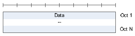
The first structure is as follows. It is data structure for TMD (TM mode data) structure. What kind of structure you see from the following diagram ?
It is Data only structure, not even with Header. Most of the data structure for any data communication has it's own header. IP packet has IP header. UDP packet has UDP header. TCP header has TCP header. ICMP packet has ICMP header, etc. But this packet does not have any header. As you know, the most important role of header is to carry the information as follows :
i) Who is the sender ? (sender address, sender id etc)
ii) Who is the reciepient (reciepient address, id etc)
iii) What is the size of the data ?
iv) etc..
But this data structure has none of these information. It means that the TMD packet does not add any additional (header) to the input data and does not split or combine the data coming into the RLC entity.
Then how the size of this TMD PDU is determined ? It is automatically set to be the same size as MAC PDU size.
What if the incoming data is bigger than the RLC PDU size ? It just take the initial part of data that can fit into its size and discard the rest of the data.
What if the incoming data is smaller than the RLC PDU size ? It just take the whole data and pass it to MAC layer and MAC layer add padding data at the end.
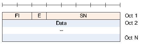
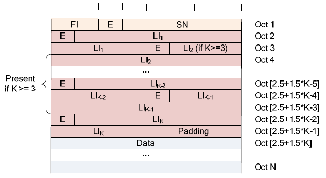
Following is a data structure for UMD (UM mode data) structure. What are the meaning of Fl, E, SN ? You should refer to other sets of diagrams later. If you remember the diagram in previous section (Fig 4.2.1.2.1-1), RLC UM entity has capability of segmentation/concatenation. It means ... if the incoming data is greater than the RLC size, it segment the data into multiple chunks and pass them one by one. In this case, you have to put some tag (number) to each of the chunks.. otherwise the receiving side cannot combine them in proper sequence. This tag (number) is SN (Sequence Number). As you see in the following diagram, there are two different types of SN. One is 5 bits and the other one is 10 bits.
What if the data coming into the RLC entity ? The simplest way is to pack the small chunk as it is (as in TM mode), but it is waste of space.
Then what do we have to do in this case ? The simplest way is to put the multiple small chunk into a single RLC packet. In this case, you need special information for each of the small chunk within the RLC packet. LI (Length Indicator) is the length value for each of the small chunks within a RLC PDU.
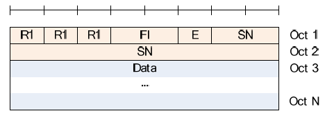
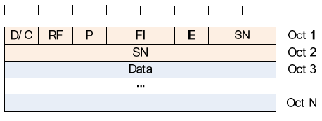
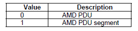
The last type of RLC packet type is AMD (AM mode data) structure. Overall structure is very similar to UMD structure except that it has a couple of additional field D/C, RF, P.
 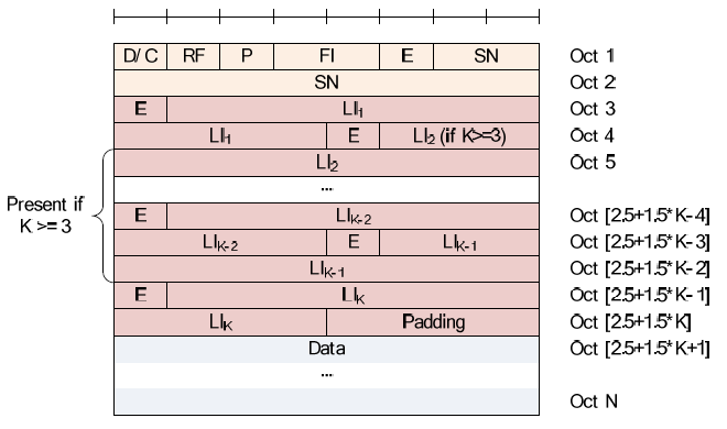 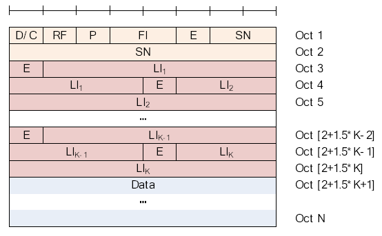 
We saw many of small fields in RLC header and now let's try understanding the meaning of each of these fields.

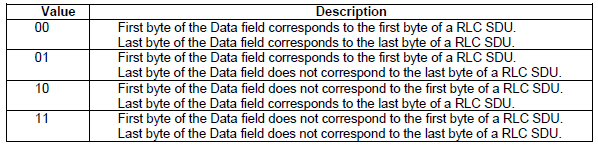
FI Field : This field indicate the relative location of the RLC PDU within a RLC SDU. For example, '01' indicate the PDU is the first segment of the SDU and '10' indicates the PDU is the last segment of the SDU, and '11' indicate the PDU is in between the first and last segment. In a SDU, there is only one '01' type PDU and only one '10' type PDU. There can be one or more '11' type PDU. If FI is 00, it means the RLC PDU is same as RLC SDU. When RLC recieves '01' type, the layer start buffering the PDU within RLC memory and only when it recieves '10' PDU, RLC reassembles all the recieved PDU and transfer it to PDCP.
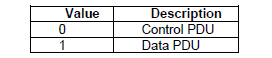
D/C Field : This field indicate whether the PDU is for RLC control or Data .
RF Field : This field indicate tye type of the AMD PDU.
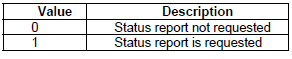
P Field : This field indicate the PDU requires a status report (RLC ACK or NACK) from the other party or not.
   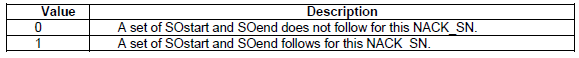
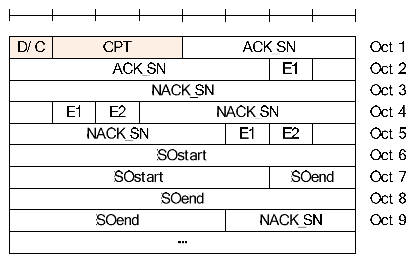
SOstart and SOend fields indicated the corresponding NACK_SN stands for 'detected as lost' which means a portion or the whole RLC PDU is lost. According to 36.322, section 6.2.2.18, 6.2.2.19 descrbes these fields as follows.
SOstart (15 bits) : The SOstart field (together with the SOend field) indicates the portion of the AMD PDU with SN = NACK_SN (the NACK_SN for which the SOstart is related to) that has been detected as lost at the receiving side of the AM RLC entity.
Specifically, the SOstart field indicates the position of the first byte of the portion of the AMD PDU in bytes within the Data field of the AMD PDU. The first byte in the Data field of the original AMD PDU is referred by the SOstart field value "000000000000000", i.e., numbering starts at zero
SOend (15 bits) : The SOend field (together with the SOstart field) indicates the portion of the AMD PDU with SN = NACK_SN (the NACK_SN for which the SOend is related to) that has been detected as lost at the receiving side of the AM RLC entity.
Specifically, the SOend field indicates the position of the last byte of the portion of the AMD PDU in bytes within the Data field of the AMD PDU. The first byte in the Data field of the original AMD PDU is referred by the SOend field value "000000000000000", i.e., numbering starts at zero. The special SOend value "111111111111111" is used to indicate that the missing portion of the AMD PDU includes all bytes to the last byte of the AMD PDU
Examples for RLC AMD PDU
Followings are a couple of RLC PDU example. In RLC PDU case, especially AMD PDU case, you should anlayze several consecutive PDUs in both direction for you to get overal picture.
With these examples, you would learn and get familiar to how to utilize all the tables/diagrams shown above.
DL AMD : A0 00 00 08 01 20 3A 90 05 1E F0 63 69 B1 F1 86 1B 25 20 3C 78 DF C6 AB B8 82 F3 93 5A B5 A7 64 80 0D 1E 79 72 F3 93 5E 35 A8 00 00 00 00
A0 00 = 10100000 00000000
D/C = 1 = Data PDU
RF = 0 = AMD PDU
P = 1 = Status PDU is requested
FI = 00 = First byte of the Data field corresponds to the first byte of a RLC SDU,
Last byte of the Data field corresponds to the last byte of a RLC SDU
E = 0 = Data field follows from the octet following the LI field following this E field
SN = 0000000000
RLC PDU = A0 00 00 08 01 20 3A 90 05 1E F0 63 69 B1 F1 86 1B 25 20 3C 78 DF C6 AB B8 82 F3 93 5A B5 A7 64 80 0D 1E 79 72 F3 93 5E 35 A8 00 00 00 00
UL AMD : 00 04 = 00000000 00000100
D/C = 0 = Control PDU
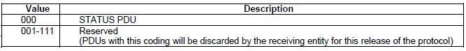
CPT = 000 = Status PDU
ACN_SN = 0000000001 (This is ACK for DL RLC SN 0)
E1 = 0
UL AMD : A0 01 01 48 01 60 EA 61 14 79 E5 CB CE 4D 6A D6 80 00 00 00 00
A0 00 = 10100000 00000001
D/C = 1 = Data PDU
RF = 0 = AMD PDU
P = 1 = Status PDU is requested
FI = 00 = First byte of the Data field corresponds to the first byte of a RLC SDU,
Last byte of the Data field corresponds to the last byte of a RLC SDU
E = 0 = Data field follows from the octet following the LI field following this E field
SN = 0000000001
RLC PDU = A0 01 01 48 01 60 EA 61 14 79 E5 CB CE 4D 6A D6 80 00 00 00 00
DL AMD : 00 08 = 00000000 00001000
D/C = 0 = Control PDU
CPT = 000 = Status PDU
ACN_SN = 0000000010 (This is ACK for UL RLC SN 1)
E1 = 0 (It means that Octat 2 is the last Octat for this RLC PDU).
DL AMD : 00 22 00 40 0C 01 C0 20 = 00000000 00100010 00000000 01000000 00001100 00000001 11000000 00100000
D/C = 0 = Control PDU (1 bit)
CPT = 000 = Status PDU (3 bits)
ACN_SN = 0000001000 (10 bits, This is ACK for UL RLC SN 7)
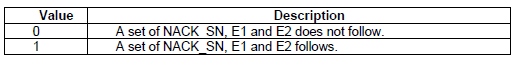
E1 = 1 (1 bit, It means that this is not the end of RLC PDU).
NACK_SN = 0000000000 = 0 (10 bits)
E1 = 1 (1 bit, It means that this is not the end of RLC PDU)
E2 = 0 (1 bit, a set of SOstart and SOend does not follow for this NACK_SN)
NACK_SN = 0000000001 = 1 (10 bits)
E1 = 1 (1 bit, It means that this is not the end of RLC PDU)
E2 = 0 (1 bit, a set of SOstart and SOend does not follow for this NACK_SN)
NACK_SN = 0000000011 = 3 (10 bits)
E1 = 1 (1 bit, It means that this is not the end of RLC PDU)
E2 = 0 (1 bit, a set of SOstart and SOend does not follow for this NACK_SN)
NACK_SN = 0000000100 = 4 (10 bits)
E1 = 0 (1 bit, It means that this is the end of RLC PDU)
E2 = 0 (1 bit, a set of SOstart and SOend does not follow for this NACK_SN)
Examples for RLC UMD PDU
This example data are captured from a RLCs for IP throughput test (in this case, video streaming test)
DL UMD PDU 1: 1C E1 06 8F CC 48 23 E9 90 DA 18 D2 2B 1B A3 D9 5C 72 E8 D7 71 A9 51 A9 82 78 17 80 DC 9B 18 76 17 99 18 48 7F 77 22 B9 8E 79 DA A9 58 5A C8 6E 1C 93 F9 1D 64 C4 58 56 46 0C B5 A3 0C 5E B3 24 49 8F F0 51 FC D7 A0 F6 29 A3 51 73 C2 31 9E F8 4B 0F 07 34 B1 06 A8 E1 79 E0 E0 DD C7 C8 FC 23 52 08 D8 F4 48 ED 9A 70 10 EF DD 1C 80 54 45 00 02 50 0E 62 00 00 80 11 95 C9 01 01 C9 37 01 01 C9 38 04 E7 04 D2 02 3C 9B 62 47 00 44 11 E6 F0 B0 1C 80 33 A5 2C 12 C2 C8 35 16 92 61 68 12 07 0D 81 CC C7 29 C9 21 A1 B9 94 6C 25 22 E3 28 78 1A 6A E3 5A 50 1B 13 83 33 C6 57 11 4D 5B 19 55 08 31 26 75 FA 4B 42 FB 84 FF 2B 1B E2 22 B3 9C 67 07 20 AC 24 07 0D 89 6B 4D 07 24 57 BC 94 CF
1C E1 = 00011100 11100001
R1 = 0
R1 = 0
R1 = 0
FI = 11 = First byte of the Data field does not correspond to the first byte of a RLC SDU,
Last byte of the Data field does not correspond to the last byte of a RLC SDU
E = 1 = A set of E field and LI field follows from the octet following the fixed part of the header
SN = 0011100001 = 225
06 8F = 00000110 10001111
E = 0
LI = 0000110 1000 = 104
Padding = 1111
SDU 1:
CC 48 23 E9 90 DA 18 D2 2B 1B A3 D9 5C 72 E8 D7 71 A9 51 A9
82 78 17 80 DC 9B 18 76 17 99 18 48 7F 77 22 B9 8E 79 DA A9
58 5A C8 6E 1C 93 F9 1D 64 C4 58 56 46 0C B5 A3 0C 5E B3 24
49 8F F0 51 FC D7 A0 F6 29 A3 51 73 C2 31 9E F8 4B 0F 07 34
B1 06 A8 E1 79 E0 E0 DD C7 C8 FC 23 52 08 D8 F4 48 ED 9A 70
10 EF DD 1C
SDU 2: (The part in color is IP address of the data going through this RLC. This IP is nothing to do with RLC itself, but it will be a good example that multiple IP packets are distributed among multiple RLC PDUs)
80 54 45 00 02 50 0E 62 00 00 80 11 95 C9 01 01 C9 37 01 01
C9 38 04 E7 04 D2 02 3C 9B 62 47 00 44 11 E6 F0 B0 1C 80 33
A5 2C 12 C2 C8 35 16 92 61 68 12 07 0D 81 CC C7 29 C9 21 A1
B9 94 6C 25 22 E3 28 78 1A 6A E3 5A 50 1B 13 83 33 C6 57 11
4D 5B 19 55 08 31 26 75 FA 4B 42 FB 84 FF 2B 1B E2 22 B3 9C
67 07 20 AC 24 07 0D 89 6B 4D 07 24 57 BC 94 CF
DL UMD PDU 2 : 18 E2 05 D2 2D 55 82 D9 82 51 91 A9 B8 BE C0 42 23 87 1B B6 1B CA B1 B6 3A 09 0E B9 64 6C B0 72 BA 74 53 A4 9D 8D 23 5C 9B 18 23 78 87 55 02 F4 07 E4 48 27 F0 8D 4A 3A 7E 09 80 8B 29 13 1A B2 7E 3C 8C 2B 9F 7F 0C AD E0 38 7E ED 40 B1 E8 73 46 62 4F 12 C8 FB 17 FC 70 FC A2 CF 85 52 A6 C3 40 4A 92 79 42 DC FE B0 47 00 44 12 E4 2A 94 21 8B DF 37 69 2F 5E D9 8A 3F 65 E8 73 D4 9A 00 EE 49 D0 AC 8E 39 7E 23 F0 F9 43 F8 1B 1E FF 0A F4 5E 7C 8C B0 F2 B3 C3 80 29 E1 3A 9E 2E A0 38 DF 3C EE 1D DF 06 BE FD 82 37 62 13 A5 F1 40 F2 D5 17 6D 99 9E 5A BF D6 AB 1D 7B 96 31 1F 31 0A 1C 24 AA 35 3D 13 00 D5 B1 97 1A BC C4 7C 7A A3 C0 9E AB AC A3 75 1D 3B 2D D5 04 AA 3F 73 73 36 1F
18 E2 = 00011000 11100010
R1 = 0
R1 = 0
R1 = 0
FI = 11 = First byte of the Data field does not correspond to the first byte of a RLC SDU,
Last byte of the Data field does not correspond to the last byte of a RLC SDU
E = 0 = Data field follows from the octet following the fixed part of the header
SN = 0011100010 = 226
DL UMD PDU 3: 18 E3 4B 8B 6C 04 16 7B A4 DA 64 E7 D5 39 A3 2A 97 15 B0 E2 4E A5 3F 1E 38 50 2E 71 B7 18 F8 D8 F6 B1 E1 39 1C 44 80 F7 E0 F8 1D 21 2E 50 BA 80 84 A2 7F 52 BF 0F 57 3A FE 42 18 E8 2C 89 8C 75 FF 28 3A 98 02 4C 47 00 44 13 3C 11 81 25 A3 1A 5E 5B F7 1A E2 F0 57 F8 A7 D1 3A 4B 82 41 B0 E4 07 D0 A3 55 2C B7 F0 F4 C1 C5 28 90 7E 15 D7 82 CC 07 FE A0 17 0E 7C AD 49 2C 48 A0 1C 23 52 A5 71 A3 D7 5E 7E 3D 1B 8B E0 CE BC 86 8E DA FA 0B F0 B9 2F 6D 3A 0F FF 64 16 EB 53 B6 9D A9 10 4B 69 25 DF 93 30 B6 F1 A4 2E 36 CF 7C F2 92 7D E3 CB 48 AB 5E AC 4F A2 00 01 18 0D 2F 28 D0 F3 A6 04 2A 8B 6A 52 B7 A1 71 A1 C7 EF C0 B0 F2 A5 C9 16 18 30 71 6A FF 47 D2 C2 C0 0D 02 50 FB 2A 87
18 E3 = 00011000 11100011
R1 = 0
R1 = 0
R1 = 0
FI = 11 = First byte of the Data field does not correspond to the first byte of a RLC SDU,
Last byte of the Data field does not correspond to the last byte of a RLC SDU
E = 0 = Data field follows from the octet following the fixed part of the header
SN = 0011100011 = 227
DL UMD PDU 4: 1C E4 02 2F 92 F1 62 09 15 25 34 19 DC E4 3D 46 DE 9A 44 A9 2B 3F CF 44 1A 36 BA B9 89 D6 14 54 F0 B5 F0 60 7C 7F 80 55 45 00 02 50 0E 63 00 00 80 11 95 C8 01 01 C9 37 01 01 C9 38 04 E7 04 D2 02 3C 6C 19 47 00 44 14 29 50 78 3D EE C9 0C 23 9E CF A4 41 4E F1 E5 6B 81 72 B2 1A 57 CD FC 39 55 29 4F 84 CF 52 79 CC A5 03 5A 1A 34 E6 30 39 C2 3F B1 E3 BE 13 99 B8 50 63 4D 45 4E 69 F8 5B 9A 46 4B A6 23 9C 8E 12 99 CD 4C B0 73 49 78 33 C6 8C 6B C1 94 9C D2 20 F3 87 61 0B EC D1 E3 FD CC 0E D1 9D 2D 20 EE 60 34 6E F6 4E 5E 41 C1 3B 06 B9 72 20 32 B2 35 30 6B 63 E8 BC 3B 27 AB D6 F5 70 B2 0D 4F 09 34 06 69 96 59 1B 37 0D C3 5B D8 2C D4 6A FA 9F 3D 5E E3 5B AF AF F0 D8 43 0B
1C E4 = 00011100 11100100
R1 = 0
R1 = 0
R1 = 0
FI = 11 = First byte of the Data field does not correspond to the first byte of a RLC SDU,
Last byte of the Data field does not correspond to the last byte of a RLC SDU
E = 1 = A set of E field and LI field follows from the octet following the fixed part of the header
SN = 0011100100 = 228
02 2F = 00000010 00101111
E = 0
LI = 0000010 0010 = 34
Padding = 1111
SDU 1:
92 F1 62 09 15 25 34 19 DC E4 3D 46 DE 9A 44 A9 2B 3F CF 44
1A 36 BA B9 89 D6 14 54 F0 B5 F0 60 7C 7F
SDU 2: (The part in color is IP address of the data going through this RLC. This IP is nothing to do with RLC itself, but it will be a good example that multiple IP packets are distributed among multiple RLC PDUs)
80 55 45 00 02 50 0E 63 00 00 80 11 95 C8 01 01 C9 37 01 01
C9 38 04 E7 04 D2 02 3C 6C 19 47 00 44 14 29 50 78 3D EE C9
0C 23 9E CF A4 41 4E F1 E5 6B 81 72 B2 1A 57 CD FC 39 55 29
4F 84 CF 52 79 CC A5 03 5A 1A 34 E6 30 39 C2 3F B1 E3 BE 13
99 B8 50 63 4D 45 4E 69 F8 5B 9A 46 4B A6 23 9C 8E 12 99 CD
4C B0 73 49 78 33 C6 8C 6B C1 94 9C D2 20 F3 87 61 0B EC D1
E3 FD CC 0E D1 9D 2D 20 EE 60 34 6E F6 4E 5E 41 C1 3B 06 B9
72 20 32 B2 35 30 6B 63 E8 BC 3B 27 AB D6 F5 70 B2 0D 4F 09
34 06 69 96 59 1B 37 0D C3 5B D8 2C D4 6A FA 9F 3D 5E E3 5B
AF AF F0 D8 43 0B
Examples from real life (Live Network)
Refer to Live Network Examples in Fullstack. You may need to put some more effort to find out RLC layer log from this example, but you will see more diverse RLC PDU/SDU structure and see the relationship between RLC and other layers.
Variables, constants and timers for RLC
You may noticed that the overall data flow of RLC sounds relatively easy to understand. But understanding the RLC layer mechanism in such a detail that would help you with troubleshooting and RLC performance optimization would not be a simple task. For the level of understanding like this, you need to understand the details of 3GPP 36.322 section 7 (Variables, constants and timers) and 3GPP 36.322 section 5 (Procedures). I would suggest to study section 7 first and then the section 5.
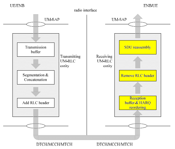
Process of RLC UM Transmission
This section is about the RLC UM transmission procedure marked in yellow below. You can see the overall description from Overall Data Flow for UM RLC
The detailed procedure is described in 36.322 5.1.2.1 Transmit operations. (To understand this description, you have all of the variable description from Variables, constants and timers for RLC)
The process is simple. If I describe it in a psuedo code, it will be as follows.
i) VT(US) = SN (Sequence Number of the current PDU)
ii) VT(US) = VT(US) + 1
Process of RLC UM Reception
This section is about the RLC UM reception procedure marked in yellow below. You can see the overall description from Overall Data Flow for UM RLC
The reception process described in 36.322 5.1.2.2 Receive operations has three different steps.
< Step 1 : Actions when an UMD PDU is received from lower layer >
This process is described in 36.322 5.1.2.2.2 Actions when an UMD PDU is received from lower layer. I will summarise the process as follows.
if ( ( VR(UR) < x < VR(UH) ) AND (SN is overlapping with any one of previous PDUs) )
OR ((VR(UH) – UM_Window_Size) <= x < VR(UR) )
{
discard the received UMD PDU;
} else {
place the received UMD PDU in the reception buffer;
};
< Step 2 : Actions when an UMD PDU is placed in the reception buffer >
This process is described in 36.322 5.1.2.2.3 Actions when an UMD PDU is placed in the reception buffer. I will summarise the process as follows.
if ( SN is Not within the reordering window)
{
i) VR(UH) = SN + 1;
ii) reassemble RLC SDUs from any UMD PDUs with SN that falls outside of the reordering window, remove RLC headers when doing so and deliver the reassembled RLC SDUs to upper layer in ascending order of the RLC SN if not delivered before
if (VR(UR) is Not within the reordering window) {
VR(UR) = (VR(UH) – UM_Window_Size);
}
}
if (the reception buffer contains an UMD PDU with SN = VR(UR) )
{
i) VR(UR) = (the SN of the first UMD PDU with SN > current VR(UR) that has not been received);
ii) reassemble RLC SDUs from any UMD PDUs with SN < updated VR(UR), remove RLC headers when doing
so and deliver the reassembled RLC SDUs to upper layer in ascending order of the RLC SN if not delivered
before;
}
if(t-Reordering is running) {
if (VR(UX) <= VR(UR) ) OR (VR(UX) falls outside of the reordering window) AND (VR(UX) != VR(UH) ) {
stop and reset t-Reordering;
}
} else {
if (VR(UH) > VR(UR) ) {
i) start t-Reordering;
ii) VR(UX) = VR(UH).
}
}
Process of RLC AM Transmission
:: Coming soon
Process of RLC AM Reception
:: Coming soon
Some issues with RLC Verification/Validation
I think one of the biggest issues with RLC test would be that most of the test equipt does not provide much flexibility in terms of RLC layer testing. Most of the equipment seems to think of RLC as just an intermediate blocks between PHY/MAC and RRC/NAS and think that just providing a normal RLC functionality as a big chunk with very limited user configuration would be good enough, and most of the customer of those equipment vendor does not put many strong requests for it. It may be OK and I haven't seen many cases where RLC layer is causing any serious issues, but sometimes this layer is really causing some problem and once the problem happens in this layer it tend to be really tricky to pin point out the root cause of the problem.
Some of the typical issues which may caused by RLC layer would be
i) When a bunch of RLC PDU/SDUs coming into RLC reciever with out-of sequence, the reciever fails to properly reorder it in correct sequence.
ii) When a bunch of RLC PDU/SDUs coming into RLC reciever with some missing sequence number, the receiver fails to detect the exact missing sequence number and send proper RLC status report to the other party.
iii) When a RLC sender send a RLC packet with Poll Bit Set, the reciever failed to reply with correct RLC status report or the status report within the specified time frame.
Probably this kind of problem would tend to occur in WCDMA low data rate configuration (e.g, R99) because there would be higher degree of fragmentation for a single C-plane or U-Plane user data packet. In this theory, LTE would have less problems since LTE can have very large data pipe that can carry a whole C-Plane/U-Plane packet with single transmission. But still there would be some possibility of RLC layer issues especially related to fragmentation and timing issues due to following reasons :
i) In real network (live network), it is not guaranteed that Network would allocate enough resource for the UE so that it can transmit a whole U-plane/C-plane packet without fragmentation.
ii) Even though the network would allocate the big enough resources for the UE, you cannot guarantee that it would allocate the resources before RLC timer get expired. (this would be less probable, but possible in theory).
|

Comments
Think on facts perceptive.